Network outline
The Collalto Seismic Network consists of ten seismometric stations and one GNSS permanent geodetic station. Figure 1 shows a map of the network, while Table 1 summarizes its peculiar features.
The network consists of ten seismometric stations with the following features:
• 1 very broad-band and high-dynamics station (ED06);
• 4 broad-band and high-dynamics stations (ED01, ED05, ED07 and ED08);
• 5 broad-band stations (ED02, ED03, ED04, ED09 and ED10).
All the seismometers are installed in well (see Table 1), while the accelerometers are installed at the surface. All the stations were built at sites of private property.
Table 1 shows the dates of beginning operativeness for each station. The network is officially operating from 1/1/2012.
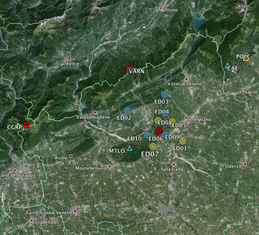
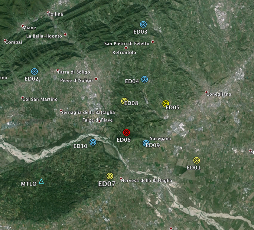
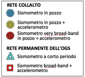
Figure 1 – Map of the Collalto Seismic Network. From top to bottom: (a) overall view, (b) monitoring area, and (c) legend. Stations of Collalto Seismic Network are indicated by circles. More details in the legend.
| Code | Lat | Lon | Elevation (m a.s.l.) |
Depth of sensor (m) |
Start date |
Name |
| 45.834582 | 12.289224 | 54 | 155 | 01/12/2011 | Susegana S. Lucia | |
| 45.905697 | 12.103050 | 205 | 33 | 01/12/2011 | Farra di Soligo | |
| 45.942908 | 12.227786 | 235 | 31.9 | 01/12/2011 | Corbanese | |
| 45.899373 | 12.229493 | 182 | 26.9 | 01/12/2011 | S. Maria di Feletto | |
| 45.880123 | 12.253799 | 110 | 14.5 | 01/12/2011 | S. Michele di Feletto | |
| 45.857011 | 12.208484 | 174 | 5 | 18/02/2011 | Collalto Campo 6 | |
| 45.822174 | 12.189355 | 167 | 14.5 | 28/02/2011 | Nervesa della Battaglia | |
| 45.882510 | 12.206460 | 193 | 14.3 | 03/03/2011 | Collalto Cucco | |
| 45.848796 | 12.231489 | 105 | 14.6 | 28/02/2011 | Susegana Castello | |
| 45.850026 | 12.170177 | 144 | 13.6 | 03/03/2011 | S. Croce del Montello |
Table 1 – Summary of the network stations. Detailed information can be found within the station files.
Stations usually consist of:
• a well equipped by cockpit and with surface access, which houses the borehole sensor;
• a cabinet, placed on the surface, which contains the electrical instrumentation and electronics;
• one or more solar panels to power;
• underground ducts for the connection between the various parts.
All stations are equipped with data tele-transmission devices and GPS antennas, for accurate time synchronization. Power is provided by electric batteries, which usually are charged by solar panels, except for few cases in which they are connected to the electrical network. Electric power is stabilized and protected from surges with appropriate electronic equipment. The cabinet hosts various equipment, such as the seismic acquisition systems, modem/router, equipment supply, battery, switches, etc., as well as the telecommunication and GPS antennas.
In order to reduce the background seismic noise and improve the signal/noise ratio, all seismometric sensors (i.e., the most sensitive ones) have been installed within a well. The depth of the wells varies from about 14 m to 45 m, with the exception of site ED01, located in the plain at the bottom of a 155 m deep well, and site ED06 which has the broad-band sensor.
According to the seismological international standard, site names are named by a 4-digit code, i.e. ED##, where ## represents a two-digit number from 01 to 10. The network has been recorded with EV code (as ED code was not available) at the Federation of Digital Broad-Band Seismograph Networks (FDSN), the international organism which manages the information of digital seismic networks and belongs to the Incorporated Research Institution for Seismology (IRIS). All information on the sites and installed equipment are recorded in the database of the OGS instrumental seismological data, called OASIS. The OASIS database website is freely accesible. Figure 2 shows the OASIS website home page.
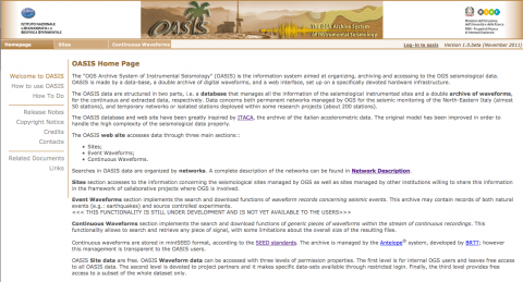
Figure 2 – OASIS website home page.