Stations description
In this section the seismic stations and their sites are described more in detail. The instrumentation is described in next sections entitled Seismometric instrumentation, Geodetic instrumentation, Data transmission system and Data acquisition and processing. Section Station files contains a detailed description of each seismic stations.
The site of ED06 station (characterized by very broad-band and high dynamics) is located within Stogit Adriatica Field 6. In addition to the seismological station, it hosts also the GNSS permanent station named SUSE. Such a couple of instruments allows to integrate directly the two kinds of data.
The seismological station ED06 is equipped with a 6-channel data logger, a broad-band seismometer (with natural period T = 120 s) and an accelerometer. For the site accommodation, an excavation up to 5 m of depth was carried out. Such a depth corresponds to a geological formation sufficiently rigid, consisting of compact argillites (Figure 1a), which represents a good basement both for the seismic sensor, and for the pillar foundation of GNSS benchmark.
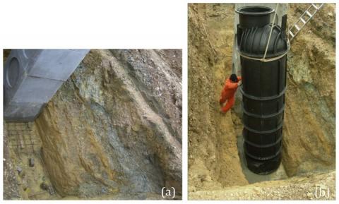
Figure 1 – Excavation carried out at the ED06 station site. (a) Excavation bottom characterized by compact argillites (of ochre colour) and cement moulds used for building the pillar of support for antenna of GNSS station (SUSE). (b) Placement of the PEMD container, where the seismometric sensors have been installed.
The seismic sensor housing consists of a polyethylene (PEMD) container, with diameter of 1.1 m and height of 4.7 m, which has been completely buried (Figure 1b). Such a container is transversally subdivided into two compartments, in order to thermally isolate the lower room, where seismic sensors are placed. On the bottom of the lower room, a concrete bed integral with the bedrock has been built, and above it the broad-band and accelerometer sensors have been placed. The upper room can be equipped in many ways. The cabin containing all other instrumentation (for security, power supply, transmission, etc.) has been sited at the surface. Inside it, also the seismic and GNSS data loggers have been placed, with the aim of facilitating access to technicians (Figure 2).
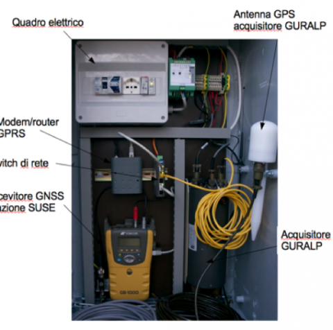
Figure 2 – Instrumentation inside the cabin of ED06 station.
For the GNSS station, a reinforced concrete plinth has been built directly on the bedrock at 5 m of depth (Figures 3 and 4). Such a plinth is completely buried and ends with a column 1.5 m high, visible at the surface. On the top of such a column the GNSS antenna has been installed. The SUSE station has been included in the precision geodetic network FreDNet, managed by OGS. The data in RINEX format can be freely accessed and downloaded at the FreDNet website (http://www.crs.inogs.it/frednet).
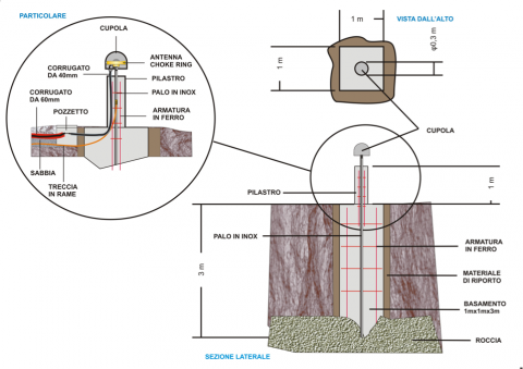
Figure 3 – Project design of monumentation for the SUSE GNSS station at the ED06 station site.
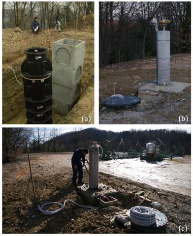
Figure 4 – Preparation of the ED06 station site. (a) PEMD container and pillar; (b) after refilling the excavation; (c) panoramic view. It is possible to recognize the column supporting the GNSS antenna and, in the foreground, the lid of the buried container, which hosts the seismic sensors.
The three broad-band and high dynamics stations (ED05, ED07, ED08) are equipped with 6-channel data loggers, compact seismometers with extended period (T = 10 s) and accelerometers. At such sites, the seismometers are placed on the bottom of a borehole with diameter of 120 mm and depth of 14-15 m, while the accelerometers are positioned on the surface. The rest of instrumentation is similar to that described for the ED06 station site. Figure 5 shows a step of well drilling at the ED08 site. Figure 6 shows some images of the preparation of the ED07 station site.
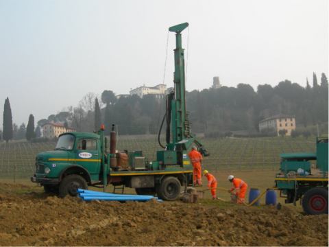
Figure 5 – Drilling of the borehole deep 15 m at the ED08 station site.
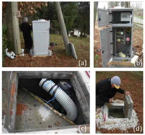
Figure 6 – Preparation of the ED07 station site. (a) External cabin; (b) instrumentation inside the cabin; (c) interior of the seismic vault, where it is possible to see the corrugated wire loom (in grey), the wellhead (in black) and the triangular concrete basement for the accelerometer; (d) superficial opening of the seismic vault.
The five broad-band stations (ED02, ED03, ED04, ED09, ED10) are equipped with a 3-channel data loggers and compact seismometers with extended period (T = 10 s). Also at such sites, all seismometers are located on the bottom of a borehole with diameter of 120 mm and depth ranging from 14 and 33 m. The rest of instrumentation is similar to that of other stations.
Finally, the broad-band station ED01 has a 6-channel data logger and a compact seismometer with extended period (T = 10 s), sited in a well at 155 m of depth. Given the peculiarity of this site, it is possible that in future additional sensors will be installed at different depths.
Given that the ED01 station is the only one with seismic sensor installed in a deep well, at the end of November 2011 a vertical seismic profile (VSP) has been exclusively acquired at this site. Such an investigation has been performed with two main goals: 1) to estimate the vertical profile of seismic velocity characterizing all the geologic formations crossed by the well; 2) to investigate experimentally the existence of ghost signals, i.e. the signal amplitude attenuation at different frequencies and depths. The survey involves recording seismic waves, generated by a source near the wellhead, through geophones placed at several depths in the borehole. The used energy sources are a mini-vibrator (owned by OGS) and a hammer striking a plate. For each different position of the source at the surface, recording has been performed at increasing depths with constant step, such as to sample the whole borehole depth. Signals have been processed and returned according to standards generally used in seismic exploration, while their analysis and interpretation are still ongoing. Figure 7 shows one example of seismic section acquired at the ED01 station site.
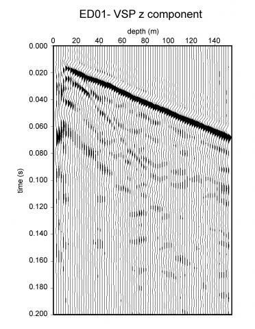
Figure 7 – Vertical seismic profile (VSP) acquired at the ED01 station site. As an example, only the vertical component is shown.